Smart Restaurant System
Applications of Robotic pathfinding in a completely digital system
What is smart? What makes a restaurant smart? These were the questions that our system was aiming to solve.
The Smart Restaurant system was a year long project of planning and and implementation split into 6 months periods.
Project Overview
The Smart Restaurant System is a large system of system system that seeks to combine various new aspects of technology to be used in a cutting edge new restaurant. The initial challenging aspect of this project was that the client didn’t know what they wanted in the system and it was up to us to give a design that they would be happy with.
A system of this size needed a team to match. Our team was made up of around 15 to 20 people changing through the project. In the design phase I was was the Testing Team Lead and in the implementation stage I was the Robot Usher Lead and a front end dev who also advised on our chosen front end technology (Angular).
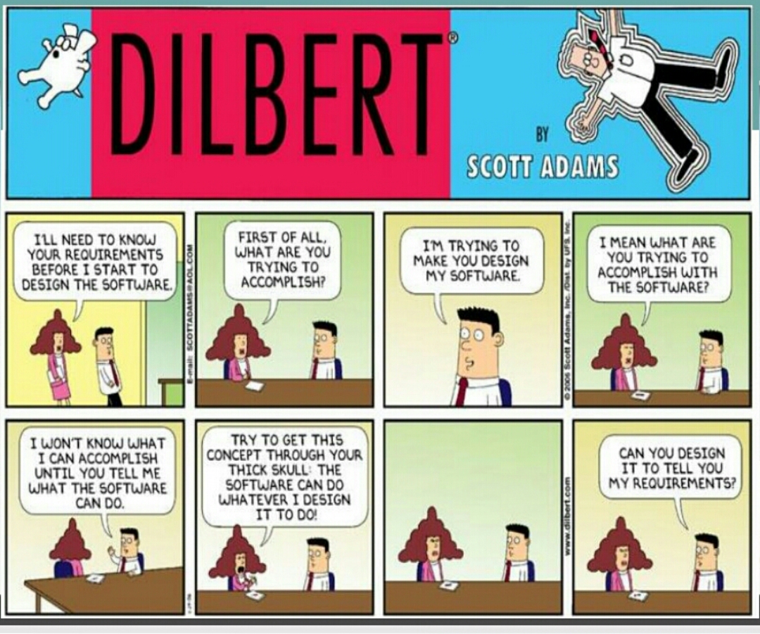
Usual tropes in Software Engineering
What’s in an Architecture
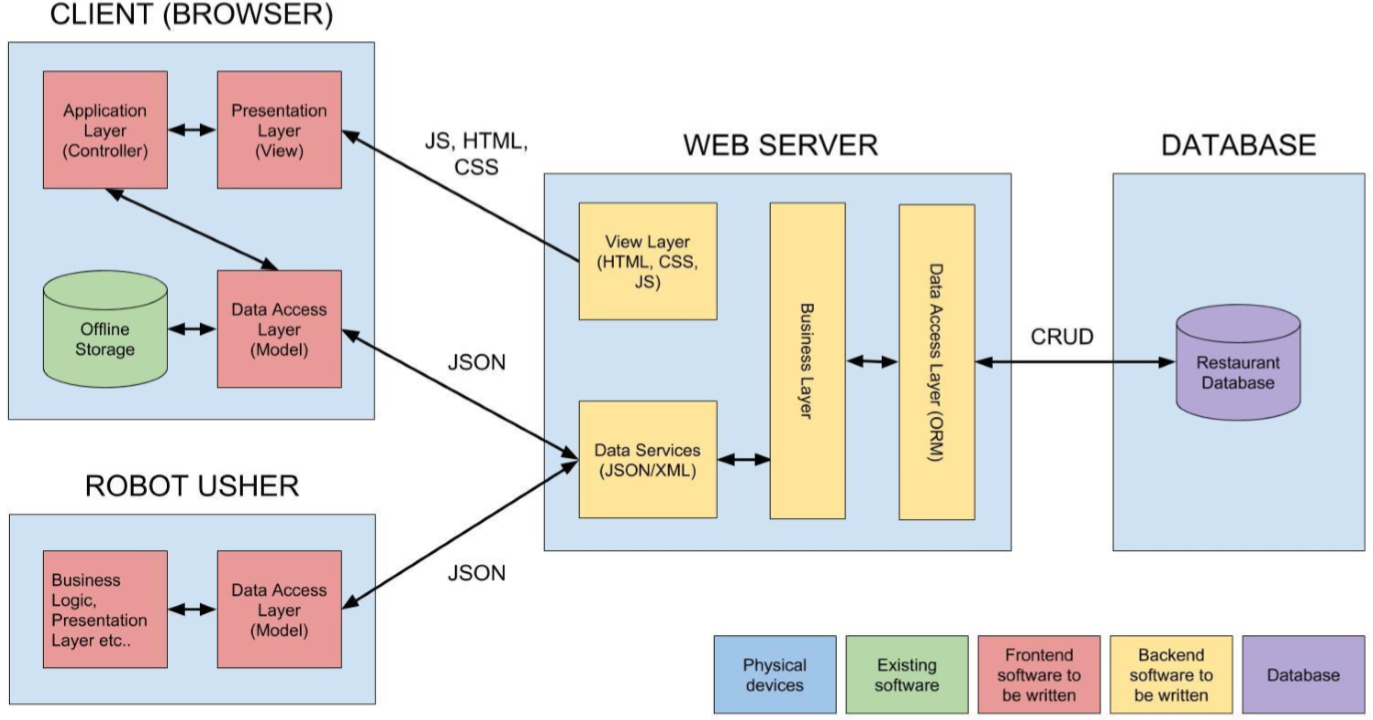
Software Architecture - Including the role of the Robot Usher
Waiters or Robots
The system was supposed to be smart and one way we could show off this aspect is by using automated robot waiters instead of traditional waiters. The client had wanted us to use their robot in the system somehow to explore it’s capability. I took on this mantle of implementing the robot system because I wanted to learn how to use software in a highly connected by robotic application.
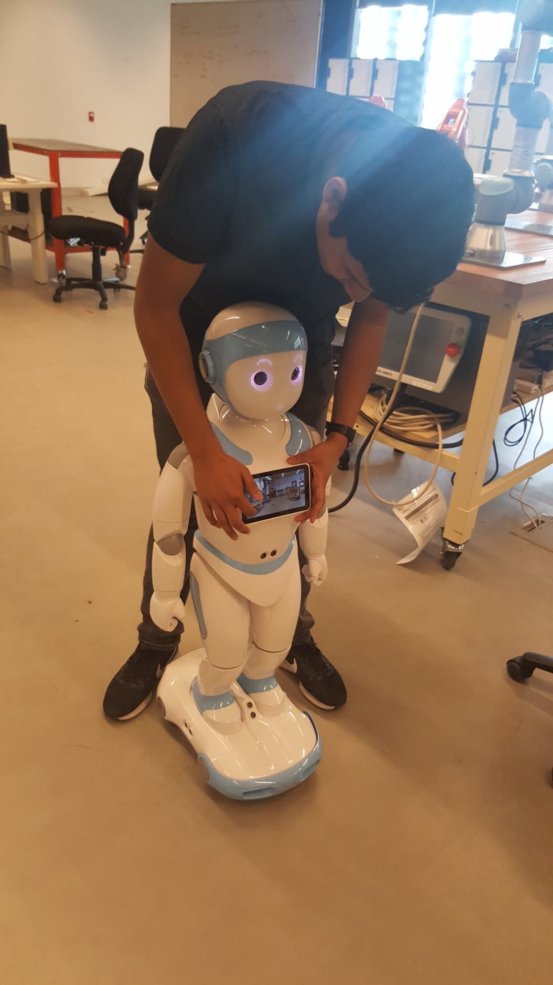
Programming the camera on the robot
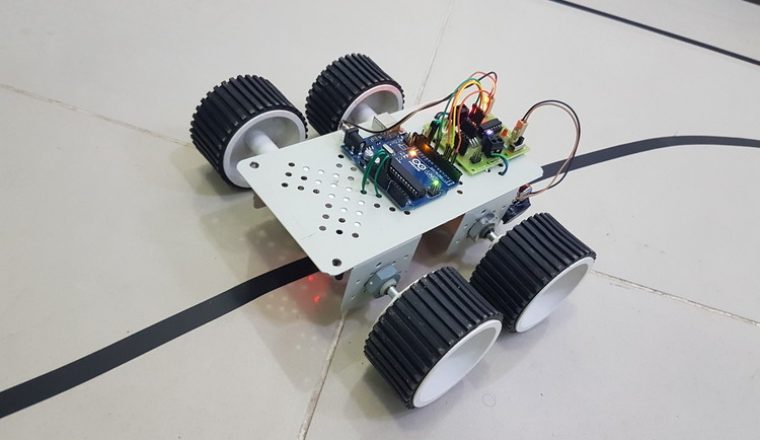
A few of the features on the IPal Robot:
- 2MP camera
- Android OS
- 3” Tablet
- Movable Wheels and Arms
- Text to Speech and vice-versa
- Short range ultra-sonic sensors
Requirements
From this point we came up with a formal list of requirements which can be summarised as:
- Greet the User at the door
- Allow the user to make a booking from the robot or retrieve their existing booking.
- The Robot must be able to guide the user to the table.
- The Robot must verbalise question to the User
- The robot must allow the user to make orders through itself.
From these requirements 4 out of 5 of them are trivial when supported by other systems. However requirement 3 posed the biggest challenge because there was no guiding.
Breaking the Problem Down
There are some considerations to make:
- We must be able to pre-plan the route before hand because the tables are at a set location
- Which means we must be able to map the environment around us.
- We have to either remember where the robot is between commands or compromise on another solution.
In short we need to map out the environment around us and track our location within it.
Mapping
Requirement 3 was interesting to me because I wanted apply the knowledge I had learned at university to a real world application as well as about robotic navigation (or localisation and mapping) in general.
SLAM
At a workplace talk I had heard about the applications of a concept called Simultaneous Localisation and Mapping (SLAM) which used advanced sensors and logic to map out the environment and then locate it within. The primary drawback of this technology is the fact that you need high quality sensors to be able to map out the environment which unfortunately meant that this technology wouldn’t fit our sensory disabled robot.
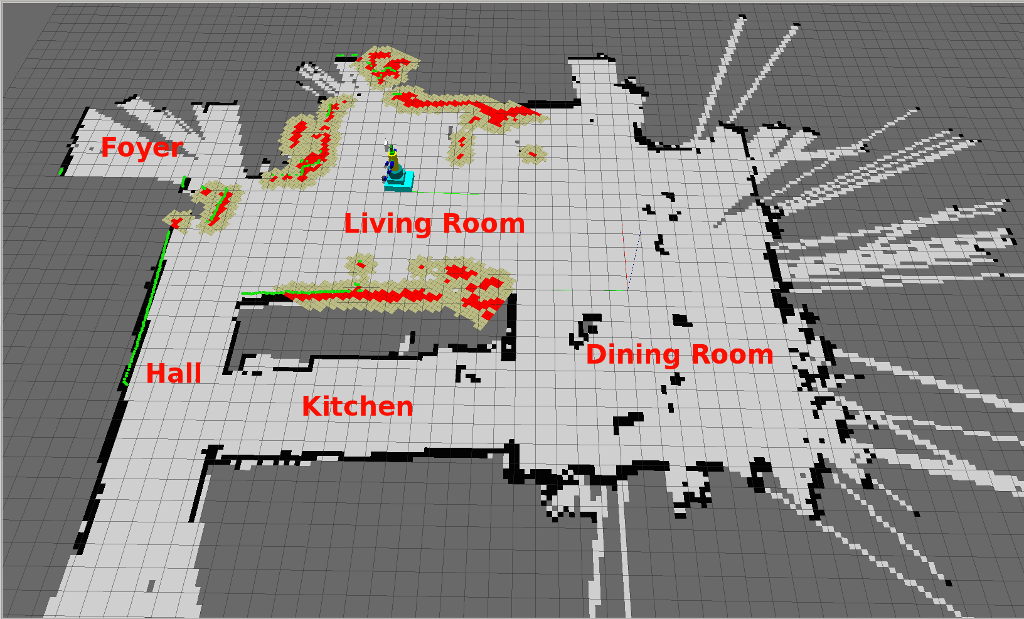
SLAM visualisation
Optical Recognition
Another approach to the problem of mapping out the environment is by relaying the information to the robot via it’s camera. I had envisioned tracks along the floor that would guide the robot to the table location. While this was a solution it also had the downside of now relying on an uncontrollable external factor. The system would become entirely inflexible if for example the table layout had to change. Later on during the design phase a dynamically changing tables though the system because a feature and this solution would no longer work. Additionally, the camera on the robot had been found as being lower quality than what we were told which would be unable perform optical recognition properly.
Optical Robot example
Summary
At this point it became obvious that the robot didn’t have the sensory capability to move around in it’s environment. However not all hope was lost because there were other ways to obtain this information. In the earlier section I mentioned a late added feature was the ability to dynamically change tables and their numbers. It occurred to me that that this system could support the robot in mapping the tables around it. While I didn’t directly solve the problem of mapping the environment a saving grace in the form of a system feature give me this information in a reliable format.
Localisation & Path Finding
Localisation within a known environment was an problem easily solved provided that you know your starting location within the area around you. Localisation is a mostly solved problem through many established algorithms. One such algorithm is the A* (A-Star) algorithm which I learned the semester before in the subject Data Structures and Algorithms.
The A-Star Algorithm
Briefly I want to give an overview how this algorithm works. It uses the concept of “nodes” connected together to form a graph. This graph has connections that change from node to node to represent the ability to move and the cost between the nodes.
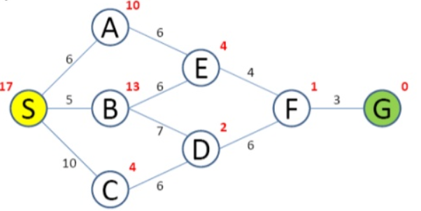
An example of a graph
Implementing the Design
Recapping from the design stage the robot uses will take it’s mapping data from the SRS system and the path finding and localisation will provided by the A Star algorithm with addition with extra tracking to keep track of location.
Prototyping the Path Finding
The table management system wasn’t complete so I used mock data and moved on to path finding using that data. As robot was running Android I started prototyping on that platform with immediate success.
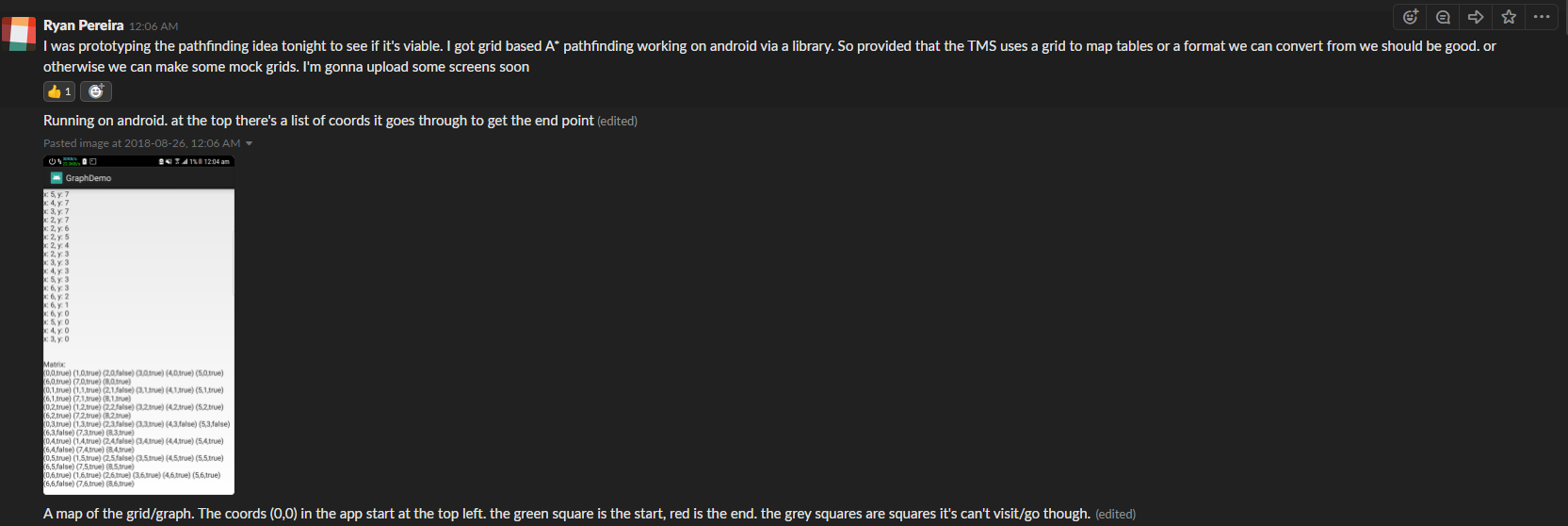
A Star on Android
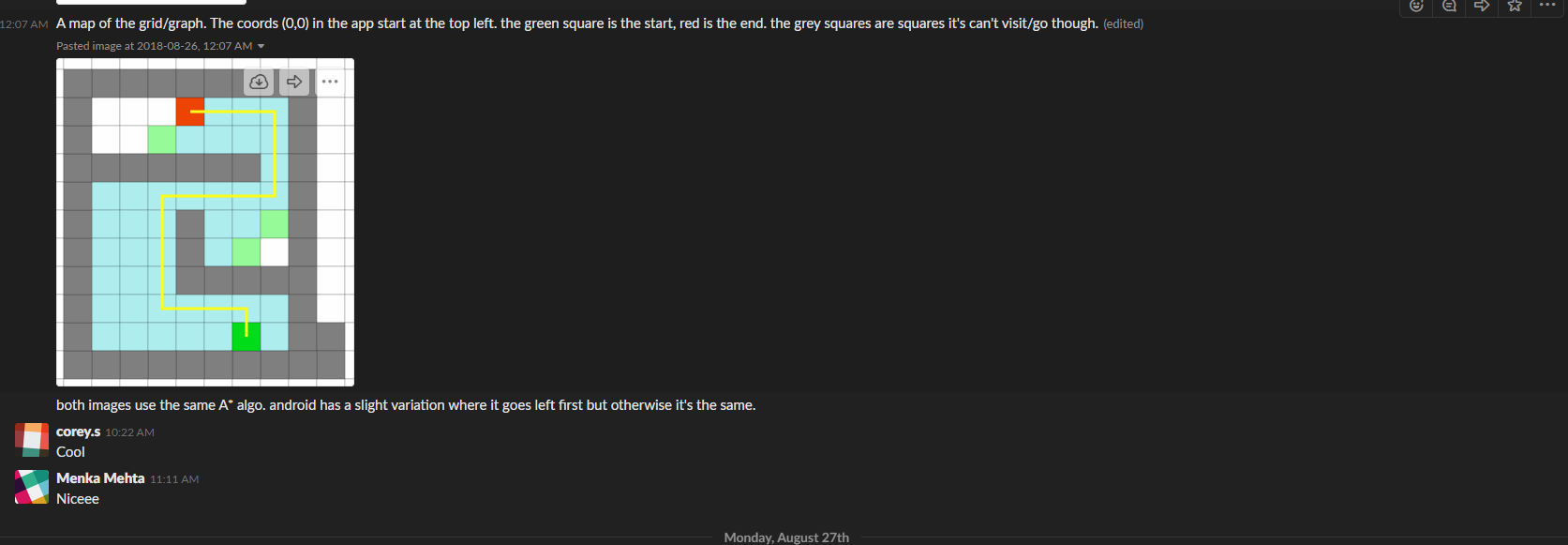
Visualised
Implementation on the Robot
On the robot the movement was implemented using the available Java IPal API’s. Some considerations & assumptions had to be made to implement this system on the robot:
- A badly designed aspect of the API however was that it operated on time to move the motors rather than distance.
- Real world distance between nodes or grids from the graph representation was going to be 1 Metre
- Diagonal movement is allowed if the software detected it
- The robot would always start at a known point
It was easy to implement it according a logical flowchart that was drawn up.
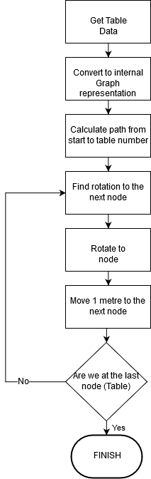
Implementation Flowchart
# IoT # Articles # Robotics # Java # PathFinding